|
How much to use or do you know what your rate is?
Definition: Shrinkage 1: drawback 2: reduction in size 3: The fractional difference in corresponding dimensions between a mold cavity and the molding made in the cavity, both the molding and mold cavity being at room temperature, when measured. **Shrinkage is often found to be different in different directions, and listed in various formats, percent, inches/inch, mm/m, etc.
In the previous article/part the example of using a part size of 1" and ABS with a shrinkage value of 0.005 per inch was used, which for that is all good. What was not stated was that in large parts with high shrinkage materials, or just critical part dimensions is that the additional material added for shrinkage has to be used in the calculations. In short one need calculate the shrink of the shrink, so to speak.
Example:
The part is 30 inches long, and shrinkage is 0.005" per inch thus in a simple method one would take 30 times 0.005" and the result is 0.150" added to part length to compensate for shrinkage. What now has to be added is the additional shrinkage of the 0.150" thus it is 0.00075" additional. Thus the resulting length for the mold to produce a part 30" long is 30" + 0.150" + 0.00075" = 30.15075". While simple and easy to follow we are still not quite there. (Yes we are splitting hairs here so to speak)
CAD way:
As a factor it appears to be complex, and as was brought to the author's attention the call out in CAD programs now use the following calculation;
Cavity Dimension = Part Dimension / (1- Shrinkage factor)
Example; 30" long part with 0.025"/" shrink
Cavity dimension = 30" / (1-0.025)
= 30" / 0.975"/"
= 30.76923"
Manual Way:
A possible standard way, which still leaves an error factor;
Cavity dimension = part dimension + (part dimension x shrinkage factor) + ((part dimension x shrinkage factor) x shrinkage factor)
Cavity dimension = 30" + (30 x.025) + ((30 x 0.025) (0.025)
= 30" + 0.75 + 0.01875
= 30.76875"
The check is to now multiply the cavity dimension by the shrink factor and subtract from the calculated cavity dimension and see if it equals what the part is supposed to be.
CAD Way: 30.769231 - (30.76923 x 0.025) =
30.76923 - 0.76923 = 30
Manual Way: 30.76875 - (30.76875 x 0.025)
30.76875 -0.76921 = 29.9995
Thus in manufacturing very critical parts the system used by the CAD is better and gives a more accurate dimension, and is in fact an easier method to calculate.
Other shrink examples:
Shrinkage of parts and deformation:
Figure 1
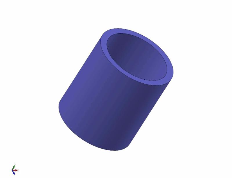
Figure 1 is a simple cylinder and shall shrink easily in length. The ID shall shrink onto the core and it may be found that running the core temperature hotter helps in ejection.
Figure 2
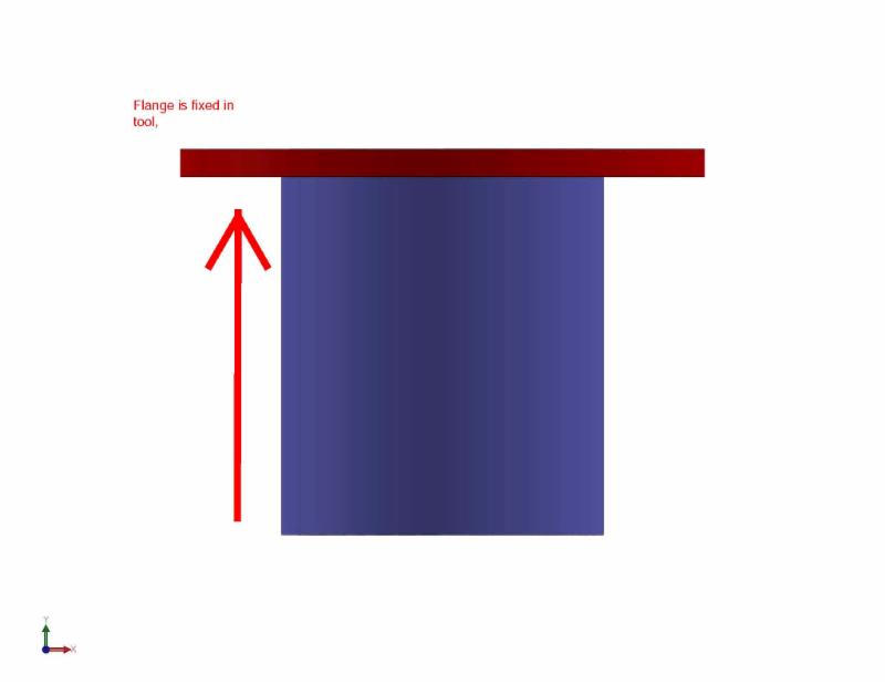
A flange is now added to the sleeve, and since the flange creates a fixed point in the tool the shrinkage is seen all in length of the un-restricted end. The relationship of the flange to the core remains perpendicular.
Figure 3
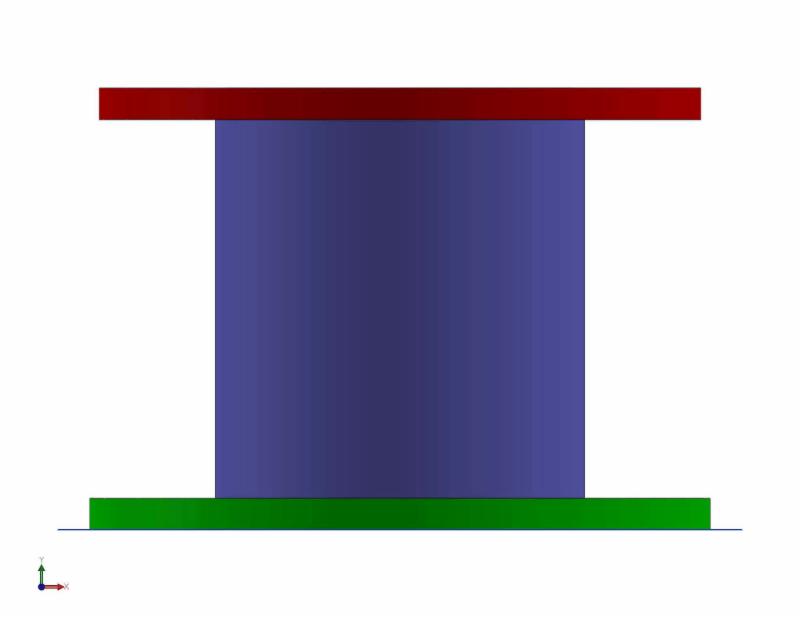
The cylinder now receives an additional flange on the other side. What now happens is that the core cannot shrink in length, or not as freely as previously. Further dependent on material used, how much it shrinks as the flanges tend to bend as the core section tries to shrink in and results in deformation of the part upon ejection from the mold and the flanges are now not perpendicular to the cylinder.
Figure 4
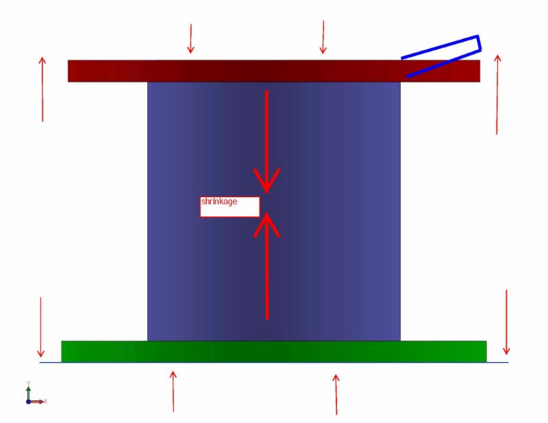
The above shows the forces acting on the double flanged part, and the area in the upper right shows the deflection that shall occur uniformly to the all flanges, though not shown.
Unfortunately this is a real world example except it started with a double flanged part, and the client wished a solution to this bending/deformation. They could get by with only one flange which is what was done, but then the issue became that the part was now too short because the cylinder could freely shrink in one direction. Further tool modifications were made for length and all were satisfied.
Thus what one has to remember is that plastic shrinks, and should there be a restriction due to flanges, holes, bosses, ribs, etc. that restricts the free shrink than the part may be bigger than thought due to this restriction. Also there may be deformation caused by the shrinkage as the part is ejected from the tool creating bent ribs, bosses, oblong holes or deformed holes as the part scuffs against the pin.
SLSILVEY
14072015
Visit our website
| 