|
where the work is performed
In part one the basic design and concept of the feed and metering sections were discussed. The center section of the screw is the compression/ transition section and this is the work area.
This section takes the material from the feed section which has the deep flights and transfers it to the metering section which has the shallow flights. The material enters this section preheated, slightly melted/soften but not completely and is now worked to complete the melting /softening of the material.
This section creates the majority of shear produced with the screw and the number of flights in this section greatly effects the shearing action. The fewer the flights the more shear which is created on the material and the greater the number of flights the less shear on the material. This section has a major influence on the temperature /work occurring in the material.
figure 1
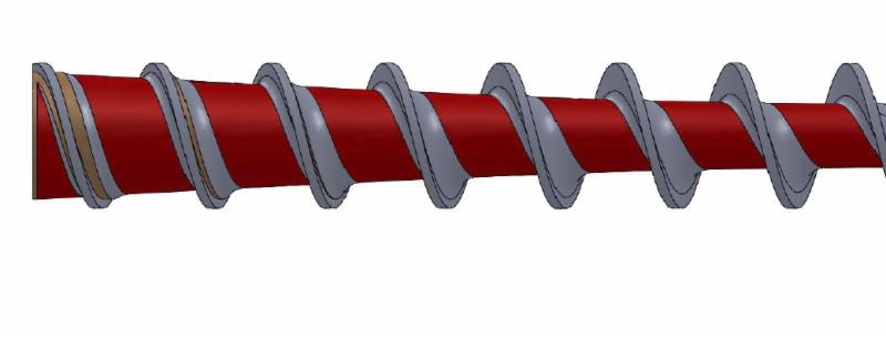
As can be seen in the above illustration the right to left flow of material is compressed as the root of the screw increase thus minimizing the depth of the flight. Note this view is an exaggeration for explanation purposes.
In general the screw section are split approximately to 50% feed, 25% compression and 25% meter. The real question comes as to what is in the machine that is being used.
In molding the design of the screw used has always been to use what a machine manufacture provides, but over the time this is changing as people realize the critical nature of the screw and its effect on the process. In extrusion they have known and worked with screws to the point that many shops have multiple screws for a machine dependent on the material they are processing.
One such design for molding which is called many different names by different manufacture is a melt uniformity screw, which basically has a different flight configuration which creates a greater curve on the back sides of the flights, and in some cases the metering section of the screw has some barrier flights/areas which create additional shearing on the melt. One great benefit of this type of screw has been the elimination of buildup, old material on the back side of the flights, minimizes purging and material contamination from material to material.
The nature of molding though is that many materials are processed possibly per shift on a single machine and a screw which accommodates multiple materials is what is required.
Some aspects to the screw to keep in mind:
- A longer feed section creates a greater potential throughput of material
- A longer metering section allows a screw to apply better pumping action in extrusion
- A shorter metering section allows less time to get a uniform mix of the melt for melt quality.
- The short compression section applies more shearing to the material and a longer section is less shearing action.
The author has found that in molding the shot size can be related to screw diameter in that 1 screw diameter is typically somewhere between 18 to 24% of the shot capacity. Thus for knowledge if the screw diameter is posted on the machine than one can look at the shot size and comparing to the screw diameter know how many diameters or what portion of the shot they are using. This is also reflected in the setup for heats on the molding machine, in that in general the settings for temperature from rear to front:
- Less than 1 diameter................ lower to higher
- 1-2-3 diameter .................. somewhat flat
- Greater than 3 diameter ................... Higher to lower
While the above are general each material manufacture may have its own range and knowing how many screw diameters are within the shot is up to the processor.
SLSILVEY
08052015
Visit our website
| 