|
Where do these lines come from or why do my parts fail?
Definition: flow line: a visual line indicating the path of flow within a part, synonym for weld line meaning where two flow fronts merge together may result in loss of strength in filled materials. Jetting: a wiggly flow of resin from a small gate or a gate not sized /located correctly to induce laminar flow in the mold cavity
In molding the issue of jetting occurs, and this can be a complex issue. What is meant by this is that in one sense it leaves a cosmetic mark in/on the part, creates unknown stresses in a part due to voids, knit lines and affects the processing conditions dependent on the type of jetting.
Generically jetting, is the effect of a stream of material pushing into a void and not impinging upon a surface to form a flow front. Thus if one were to run a short shot the results would be a ball of string, a wiggly pattern or even a straight line of material. This is all the result of jetting, which is a result of cavity wall thickness, gate placement and gate thickness.
Examples:

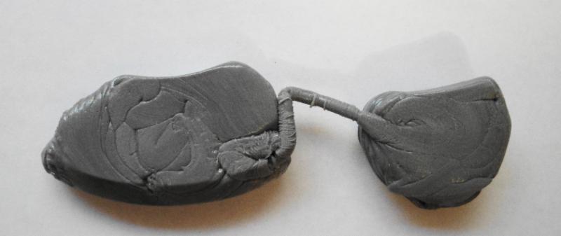
The above is the back side of the part opposite the gate, this part is gated in two places, as observed above does not seem to be balanced, one can see the flow of the material, and how it is packing out in the one side over the other. Further as the part fills in the area between the flow ribbons shall try and pack out but the captured air in these areas shall prevent a smooth finish.

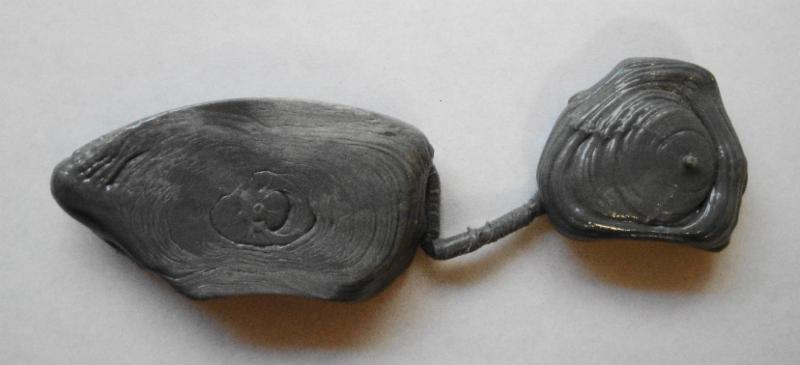
This is the top view or gate side as one can now see the size of the gate and parts. While it can be noticed that the material is flowing or looks to be flowing on this side all one has to do it look at other side (previous photo) which has different pattern. The gate is 1/16" (1.57mm) in diameter while the wall is 0.625" (15.7mm) thick, by 1.4" (35.26mm) wide.

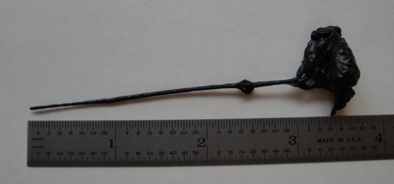
This example shows that the material actually traveled over 3" in the cavity before starting to build up a flow front. This was only in one cavity of the 2 cavity mold.

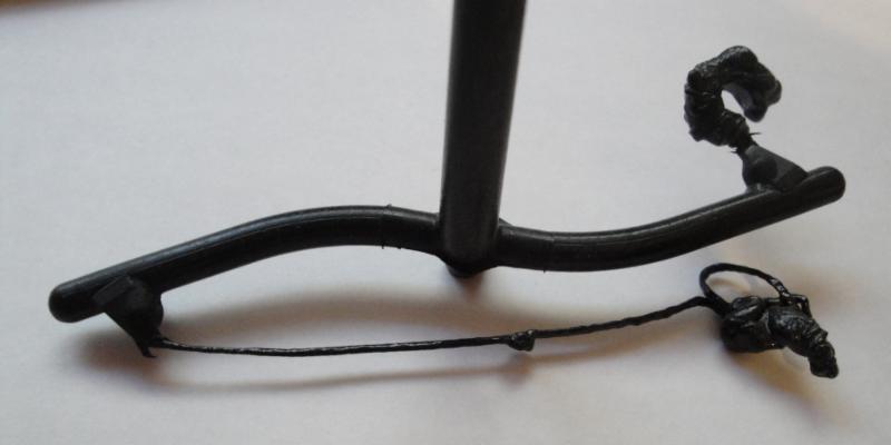
As can be seen in this view one cavity has an issue worse than the other cavity, both of which are producing the same identical part. One would than wonder if the physical strengths of both parts are the same, and given the issues the cosmetics on the parts are different. Both cavities are jetting but in different modes / results.
In each of the above examples the gate location / cavity thickness/ and placement of the gate contributes to the resulting issues. In both cases the real issues were the lines in the part, which both molders would try to make better by mold temperature adjustment, injection speed and numerous other techniques to eliminate though always fail.
From the processing side many well slow down the injection speed, may increase steel temperature, and melt temperature to in effect change the results which were designed into the part by a designer.
From a process point, what one may see on the graph is that the pressure curve flat lines for a bit or even decreases downward after going through the gate. The gate in fact is the regulator of flow of material into the cavity. This is due to the fact that the gate is possibly the smaller orifice in the feed system and due to this the pressure does not increase until there is resistance in the cavity which than results in the packing out of the cavity.
Meanwhile while filling the cavity without a resistance to flow into the void of the cavity the stream of plastic material is cooling off, which results in the cooler material, thus possible voids in the part and in general similar to a ball of twine, in that one can see the individual flow through the gate.
In some cases it is what it is, meaning that it was the only way to manufacture the part, and the part functions/ performs to specifications and all are happy, that is a good thing, while in other cases the folks are all upset because the part does not perform or function or has cosmetic issues. In these cases one has to determine how to fill the part with a flow front, moving the gate location, changing size of gate, using a profiled fill, and or other techniques or tool modification to introduce an impingement point so as to create the flow front.
Another possible solution involves the use of hot and cool on the mold temperature, systems such as RocToolŽ, Engel's Variomelt process and Singles system are but a few of the processes, an introduction has been publish (older) and may be found here: http://www.ptonline.com/articles/hot-cold-thermal-cycling-of-injection-molds-heats-up
SLSILVEY
15032015.01
Visit our website
|