|
why does the part break in use?
Definition: something not correct in the design of the part, and or issue which results in failure of part due to design, and or manufacture methods
The following is an actual problem in a plastic part design, which replaced a coupler in an automatic, skylight window. This was not something that I was called into as a consultant but rather something I had to solve within the house I sometimes reside.
In part design there are many rules of thumb, some of which have been covered, and this one has to do with actual usage of the part. One must understand the use of the part in the field, what is the environment of the part, and by environment, it is not only temperature, sunlight, moisture and so forth but also load that is to be applied and how much and what is the cyclic function, meaning rotation, load etc..
In the part in question, its function is to act as a shear / universal joint between the motor and the actual drive mechanism, coupling the output of a motor to the impute of the drive mechanism. It also aids in a minor alignment of the two. If the part fails, than the window is stuck in the position it is at point of failure.
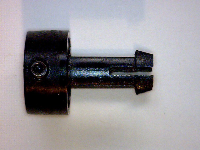
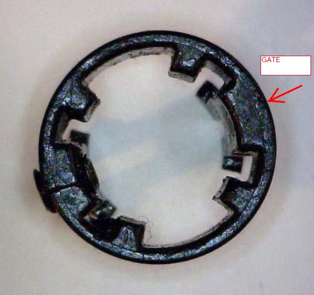
The part is of a non-uniform wall design, meaning that wall thickness varies and there are some snap fit functions for joining of the parts. The gate is a submarine type, self degating, into thickest point and this places the weld line 180 degrees opposite. Also there is a drill hole/ or molded hole which is tapped that a small allen head set screw is fitted into.
Unfortunately this is located at the weld line.
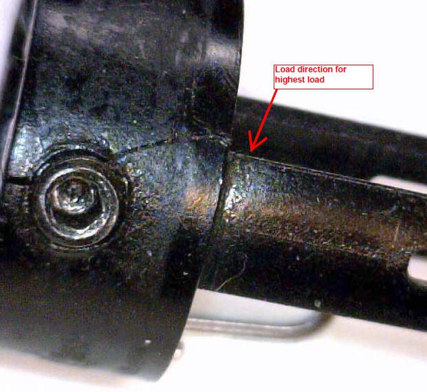
Problem #1, Set screw area is too close to edge of part, about 1/8 diameter or less
Problem #2 Set screw is located on the weld line
Problem #3 sharp corners at area of load
As the following photos show the issues, a picture is worth very much. The overall problem may have been in that someone changed from one manufacturing type to another, and or was concerned that the assembly in the field would be better with a set screw. While the function of the part seems to work in the short term, and other factors may play a large part in its performance from a personal standpoint on this particular window, this part has been replaced numerous times.

A side view is shown above with set screw.

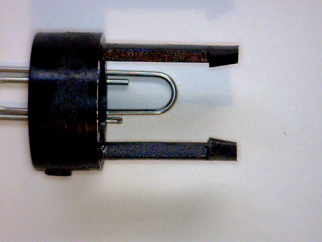
The above is a rotation of the side view by 90 degrees.

As seen above the set screw is close to the edge and breaks on the outside where one would expect the weld line to be, and then there is also the crack up to the other side which is a sharp corner and locks into the other mechanical point, meaning there is a load on this point.

In the above it is showing the wall thickness variation, though the part appears packed there are flow lines around the gate area.
The material for the part tested to be a nylon type by simple burn test, and it does appear to have filler content, which is low. The wall thickness between thick and thin is 1.3 mm to 3.4 mm. The simplest fix may have been to move the gate to one of the other ribs, and an additional fix is to watch how one drills out the hole for the tap and to use a properly design tap with proper feed rate for this plastic.
Venting on the tool, mold temperature and other processing issues may all come into play but since this is an example of an issue where one does not know how it was manufactured they would only be guesses.
SLSILVEY
10012015
|